Site Survey
Topic 2: Site survey
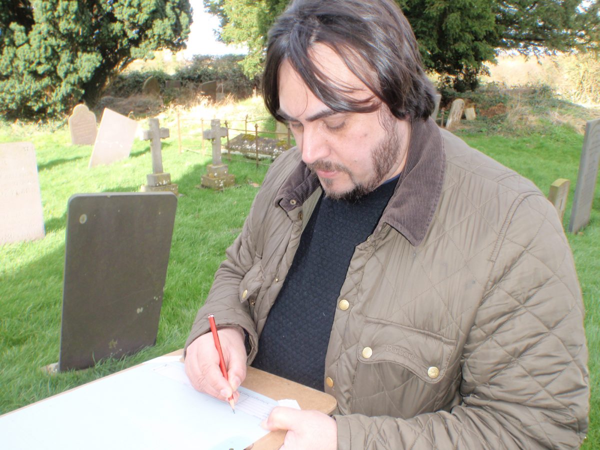
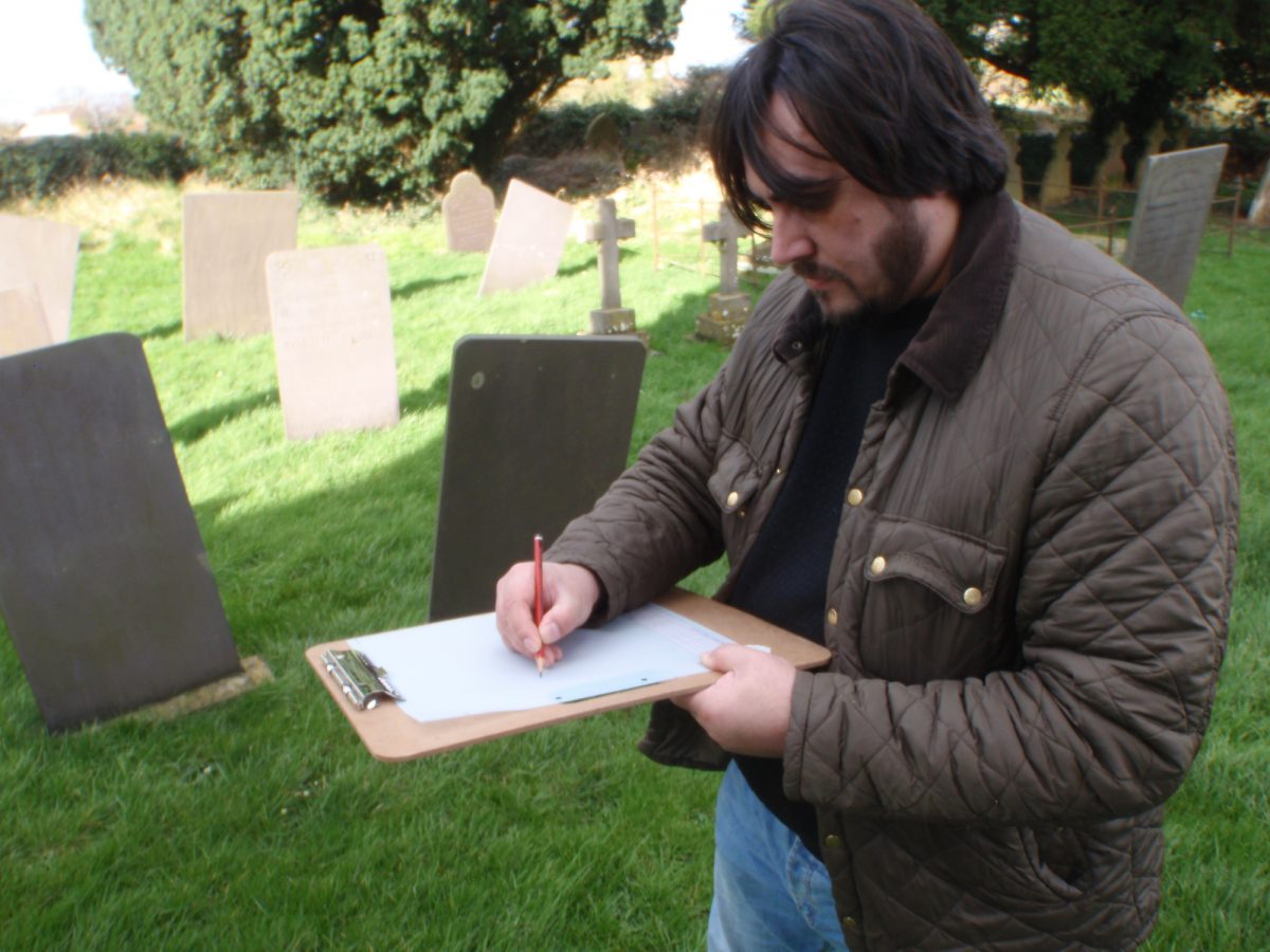
This section will show you how to measure, plan and draw things of interest that you find.
Drawing
Planning or measured drawing can be done in a variety of ways, depending on the equipment available and the type of site you are drawing.
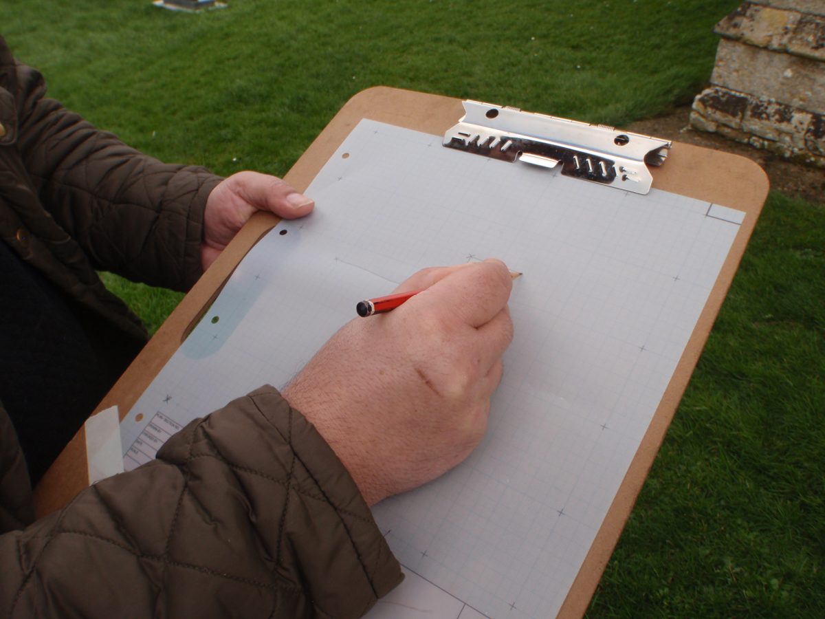
Drawings of landscape features are usually drawn to scale. The most common scales used are 1:10, where 1mm square on a sheet of graph paper is 1cm on the ground; or 1:20, where 1mm square on the graph paper is 2cm on the ground.
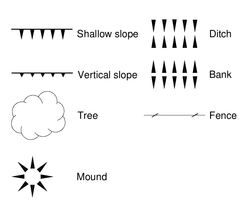
When making drawings it is handy to have a set of drawing conventions that are quick to draw, consistent and recognisable. In the image below you will find some of the most common line types and symbols.
Equipment
As part of the Layers of History legacy, there will be basic surveying equipment available to loan to interested groups and individuals for further archaeological recording.
Offset measurement
This is one of the more basic methods of drawing plans, and uses the least amount of equipment. You will need:
- at least one 30m tape
- a 3m or 5m hand tape
- some six inch nails
- a bulldog clip (or two)
- a pencil and some graph paper (although gridded drawing film more durable)
- a drawing board
1
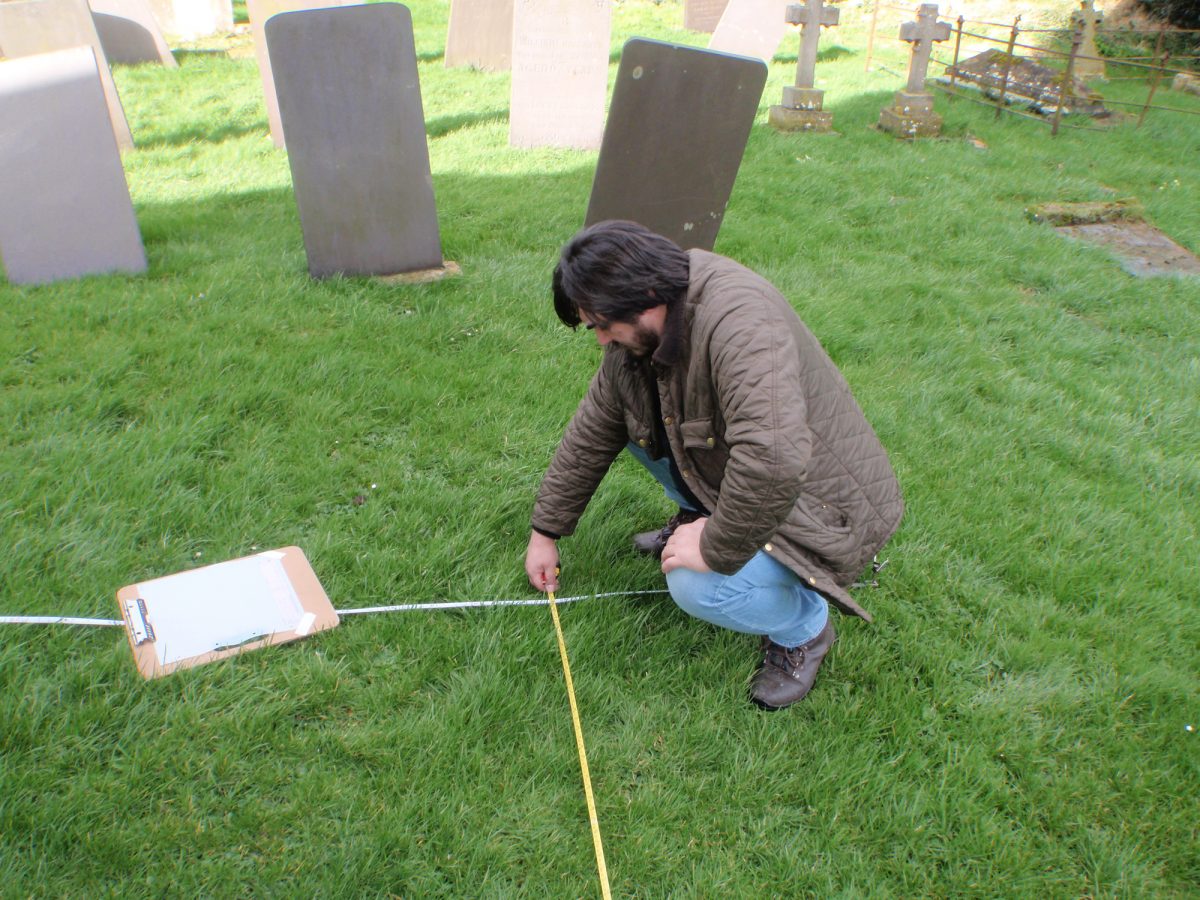
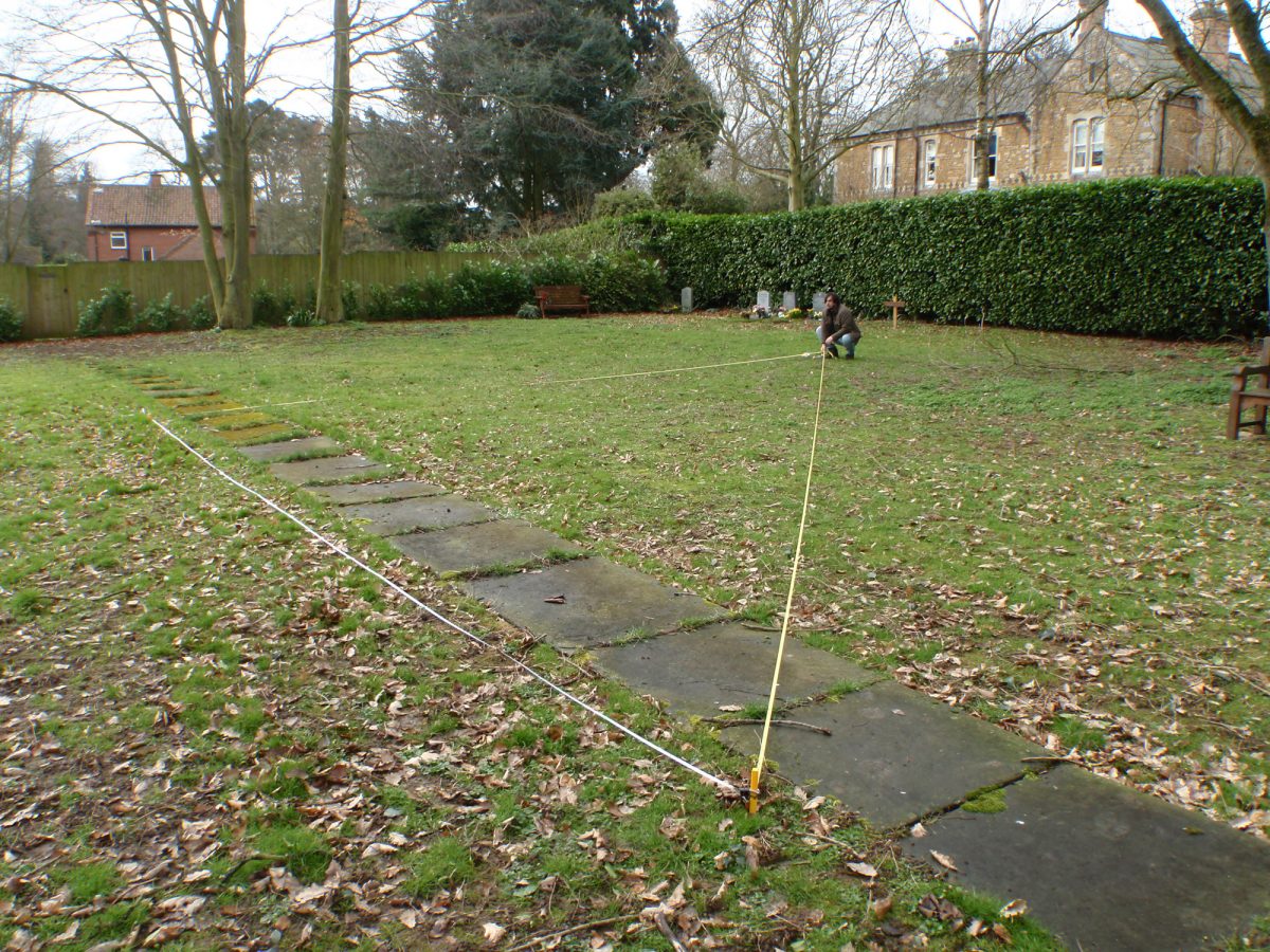
If you are drawing a small area (less than 30m long by 10m wide) then you can start by extending your 30m tape either over the middle of the thing you want to draw or along the side, securing both ends with nails and bulldog clips. Look along the tape to make sure it is straight and taut. Now mark each end of the tape on your graph paper with a cross, this is your base line.
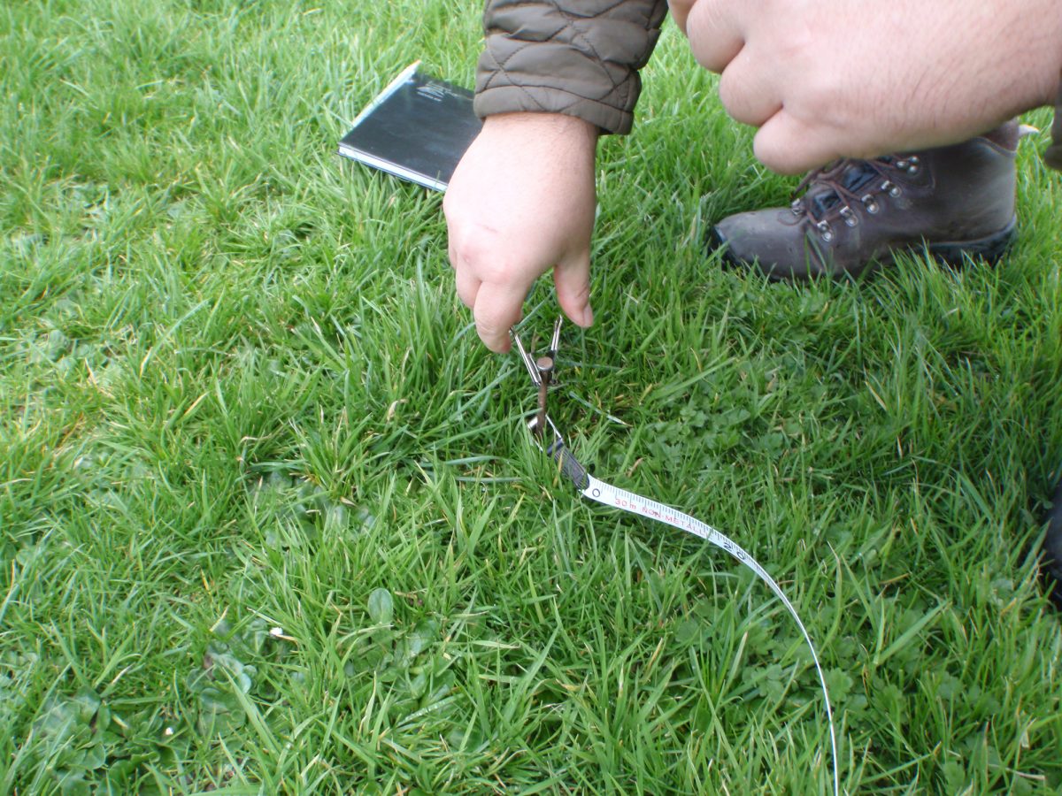
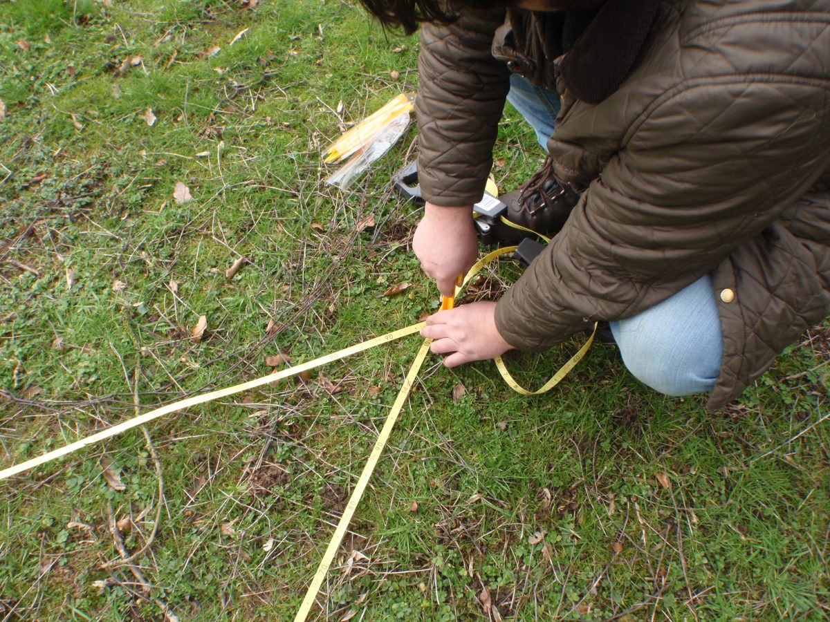
Setting up one end of the tape with a nail. The bulldog clip prevents the tape slipping off.

Putting in a nail to secure the other end of the tape.
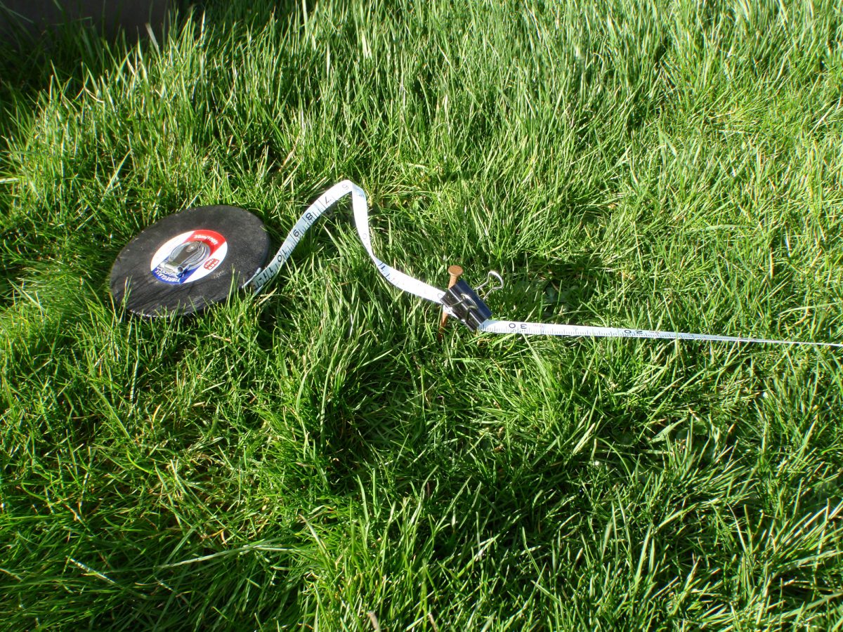
The tape is held taut with a bulldog clip.
2
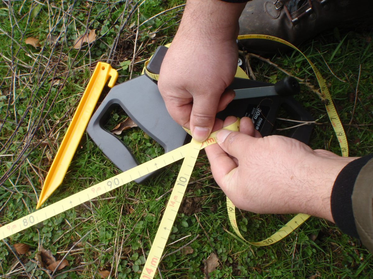
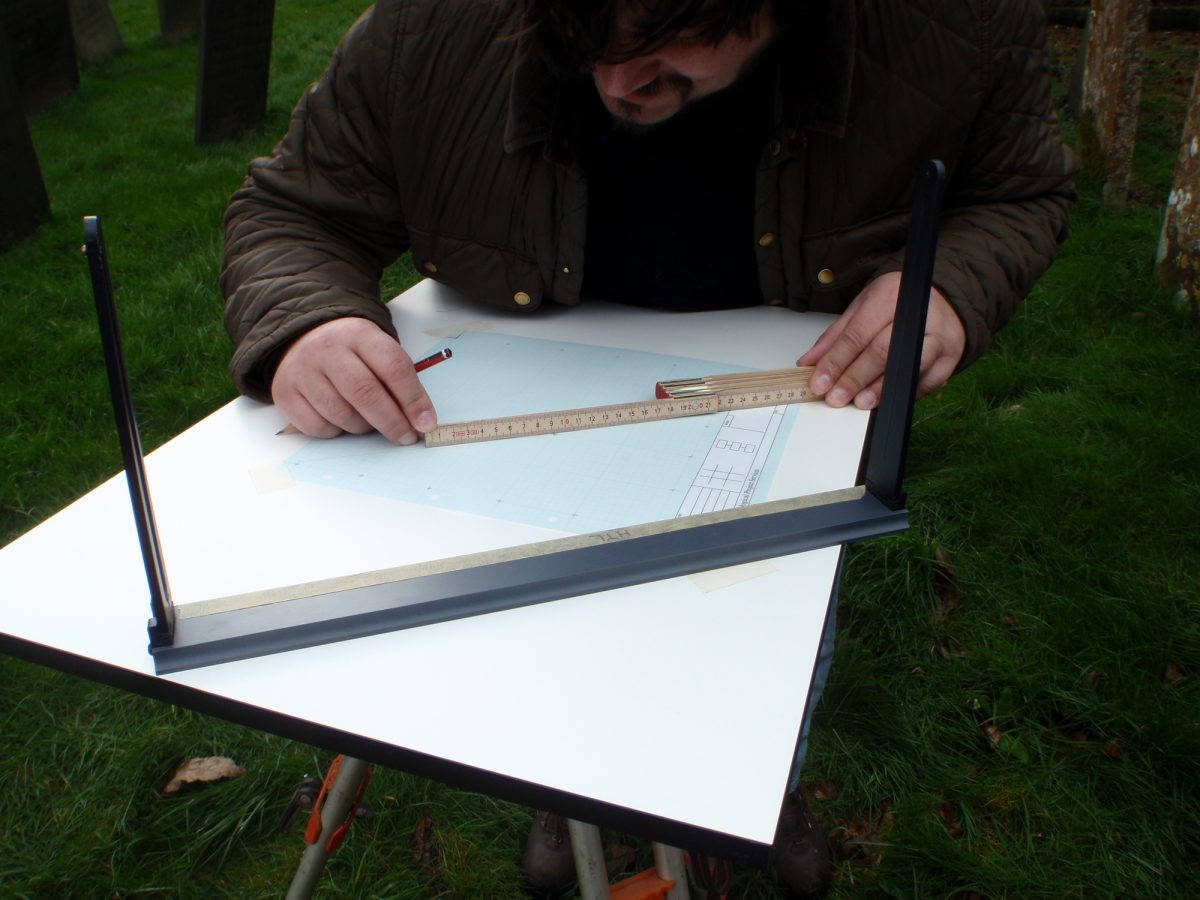
Select a prominent point on your feature. Extend your hand tape, until the end reaches your selected point, now ensure that the angle between your hand tape and your 30m tape is a right angle.
3
Now you can take a measurement. Note the distance where the hand tape crosses the 30m tape, this is how far along your base line you need to measure on your graph paper. Now note where the 30m tape crosses the hand tape, and measure that away from the base line at the distance along, previously measured. Put a dot at that point.
4
Repeat this until you have measured in enough points along the side of the feature to draw its shape on your graph paper:
5
When there is a larger area to plan, either you need to set up more than one base line, or use a different method. To set up a second base line you will need three 30m tapes.
6
Having already established your first base line, a perpendicular line can be measured off as follows:
Attach a second 30m tape to the zero point of your base line and secure a third 30m tape to the nail put in the ground 10m along the base line.
Now measure 10m away from the zero point and 14.14m from the 10m point and mark this position with a nail.
Now measure 20m from the 20m point and 28.28m from the zero point and mark this position with a nail. You now have a 20m by 20m square.
7
You can now either divide this square up by measuring between your nails or you can use the positions of the nails as known points to extend your lines. This is done by eye, although you might find it easier if you have something brightly coloured on the nails to help you line things up.
Triangulation
Triangulation is a very handy method of locating discrete objects such as gravestones or posts. It requires essentially the same equipment as offset planning, but you will need at least two 30m tapes, a pair of compasses and a ruler, ideally a scale ruler.
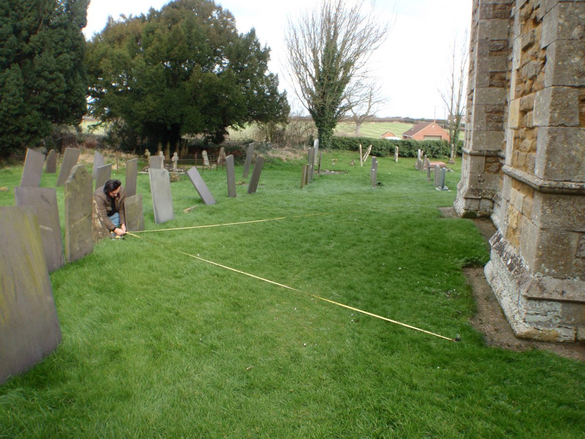
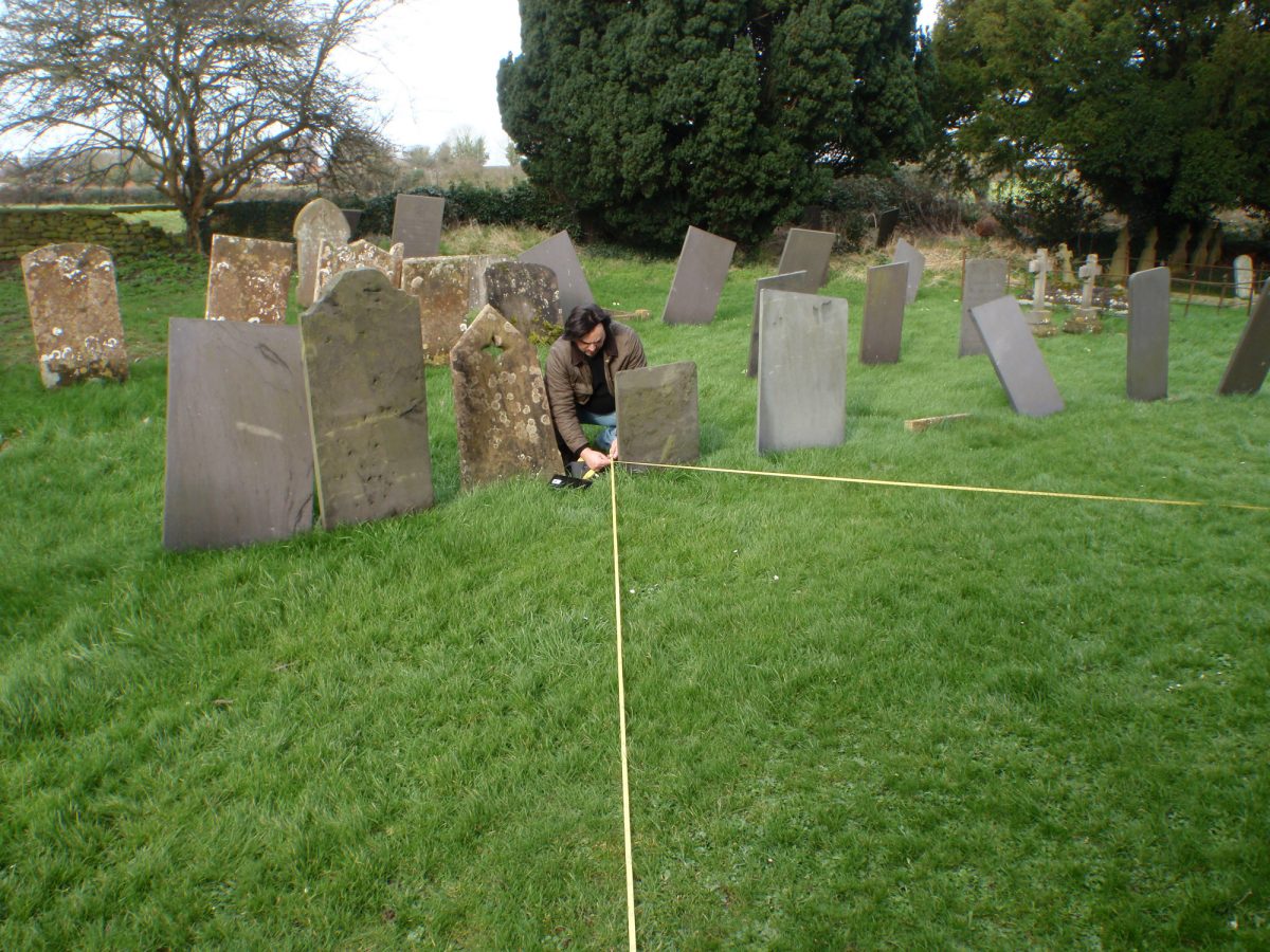
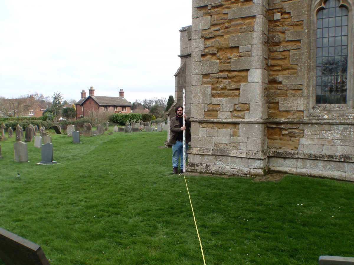
Triangulating from the end of Harlaxton Church. The nails wouldn’t go into concrete, so they are a measured distance from the buttress corners.
The first thing to do is decide whether you are surveying from points visible on a map, or setting up two base points a set distance apart. The first method is ideal when you have a map or plan available to annotate, whereas the second can be used to start a plan from scratch.
If you are using points on a map, make sure you can measure from those points to the objects you are planning.
1
Using six inch nails and bulldog clips, secure the end of each 30m tap to your map reference points. Extend both tapes to the point you wish to locate.
2
At this point I find it useful to make a note of the measurements from each point.
3
Using a ruler, set your compasses to the scale distance equal to one of your measurements. Now, making sure you have placed the compass needle on the right point on your plan, draw a feint line roughly where you think your point is. Repeat this with the second measurement, drawn from the other point. Where the two lines cross is the point you are trying to locate. You can repeat this for each point, until you can trace the outline of any features that you have. If conditions on site are difficult, you can make a note of your measurements and draw them onto your plan when you have returned home.
On those occasions where you do not have a plan, it is better to put down two points a set distance apart (5m, 10m, etc…). The method of measuring points and drawing them is essentially the same, except that you begin by drawing your base points on your graph paper, at the appropriate scale distance apart. With this method, it is useful to draw in the boundary of the property you are in, so that you can locate your drawing on a map at a later date. NB This method can be used to locate any base lines you have used for offset planning.
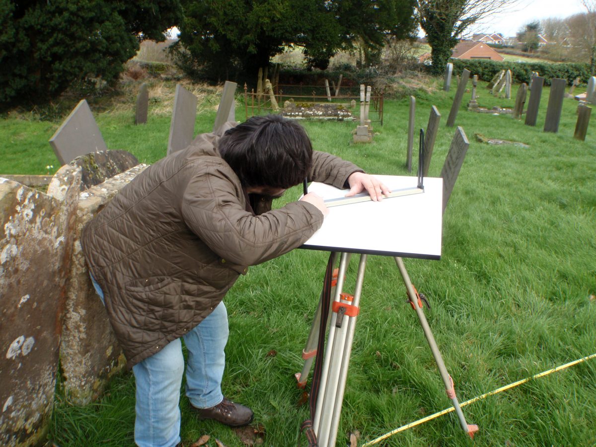
Plane Table survey
The plane table is a traditional, and often overlooked method of surveying, but it has the advantage that it requires little equipment, and can be improvised if necessary.
To carry out a detailed survey you will need; a plane table, tripod, plumb line, a ruler or scale ruler, alidade, spirit level, several six inch nails, bull dog clips, a 30m tape, a 2m ranging rod, a pencil, graph paper (ideally drawing film) and masking tape.
The first task is to decide whether you can survey your area from one place, or if you will need to move position.
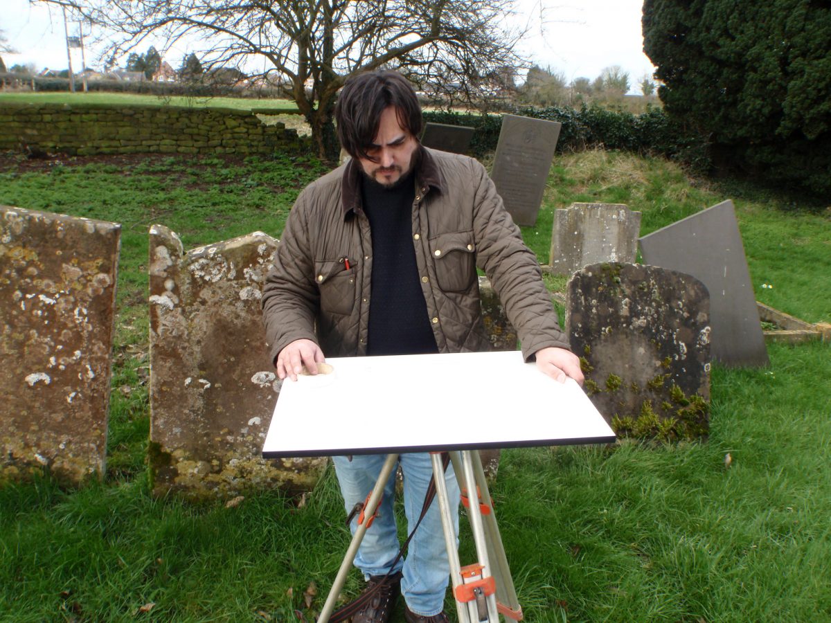
If you can survey your area from one place, set your tripod up approximately in the middle of the area, where you can get a clear view of everything. Using your spirit level, get the top of the tripod as level as possible by adjusting the height of the legs.
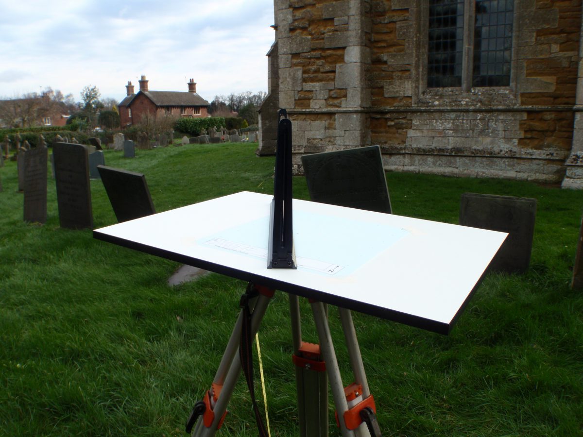
Now attach the plane table, with the drawing film taped on it, to the top of the tripod and make sure it is level, it also helps if one of the sides is aligned north-south.
Using a plumb line, mark the ground below the table with a nail, secure the end of a 30m tape to the nail with a bulldog clip. Mark the position of your table at the centre of the drawing film with a dot, surrounded by a triangle.
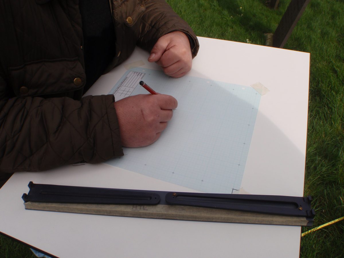
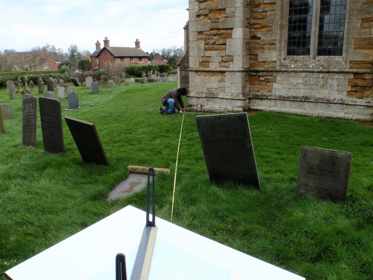
This is the point that all your measurements will be drawn from. Choose the position of the first point you wish to locate, you may need to mark this with a 2m ranging rod. Now, place the edge of the alidade on your centre point on the plane table and, looking through the slit in the eye vane, rotate the alidade so that the thread in the object vane lines up with the feature or ranging rod.
Checking that the edge of the alidade is still touching the centre point, draw a feint pencil line.
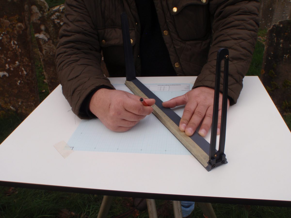
Now measure the distance from the centre of the plane to the feature.
With a ruler or scale ruler, measure the scale distance along the line to the point and mark with a cross.
Repeat this process for each point until you have an outline.
If you have to move position, select a new position you can see from your current position and mark it with a nail. Use your ranging rod and 30m tape to locate this on your plan (dot and triangle). Now move your plane table over the new point (but leave your last base point in), using your plumb line to make sure the centre of the table is directly over the nail. Fasten your 30m tape to the nail. Now adjust your drawing film so that the new position of the table is in the centre of the board and sight back to your previous base point and make sure that your plan is properly aligned. Fasten your drawing film with masking tape. You can now continue your survey using the new base point.
Radial line plotting
Radial line plotting uses the same basic principle as a plane table, but uses a dumpy level to measure the direction of the point, rather than drawing directly onto the plan.
For this method of surveying you will need; A dumpy level, a tripod, a level staff, a 30m tape, nails, bulldog clips, notebook, pen, drawing board, pencil, graph paper or drawing film, and a 360 degree protractor.
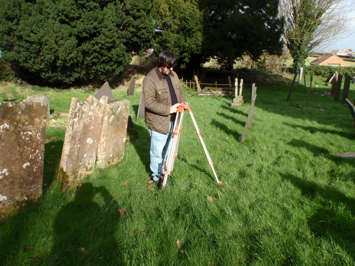
First you will need to select a base point for your survey, and set up your level. Set up the tripod so that the level will be a comfortable height to look through.
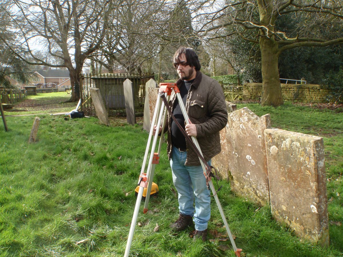
Make sure the top plate is a level as possible. Now screw the level on, with the each of the footscrews located over a tripod leg.
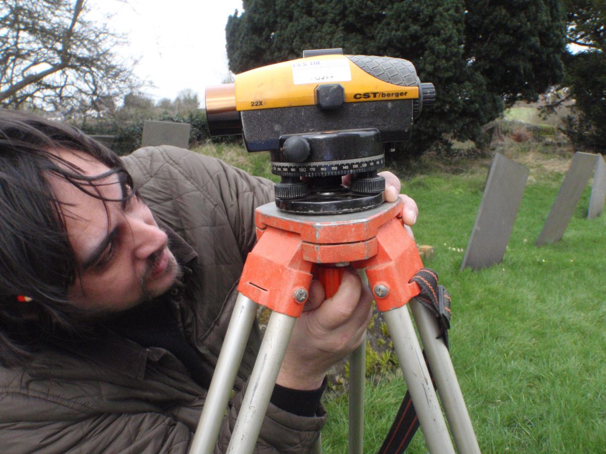
The footscrews allow fine horizontal adjustment, and a bullseye spirit level will tell you if the instrument is level. First adjust the two nearest of the screw feet, turning them either towards each other or away from each other until the bubble is in line with the centre of the bulls eye.
Now adjust the third footscrew, until the bubble is in the centre ring. You may need to go back and adjust the first two footscrews again.
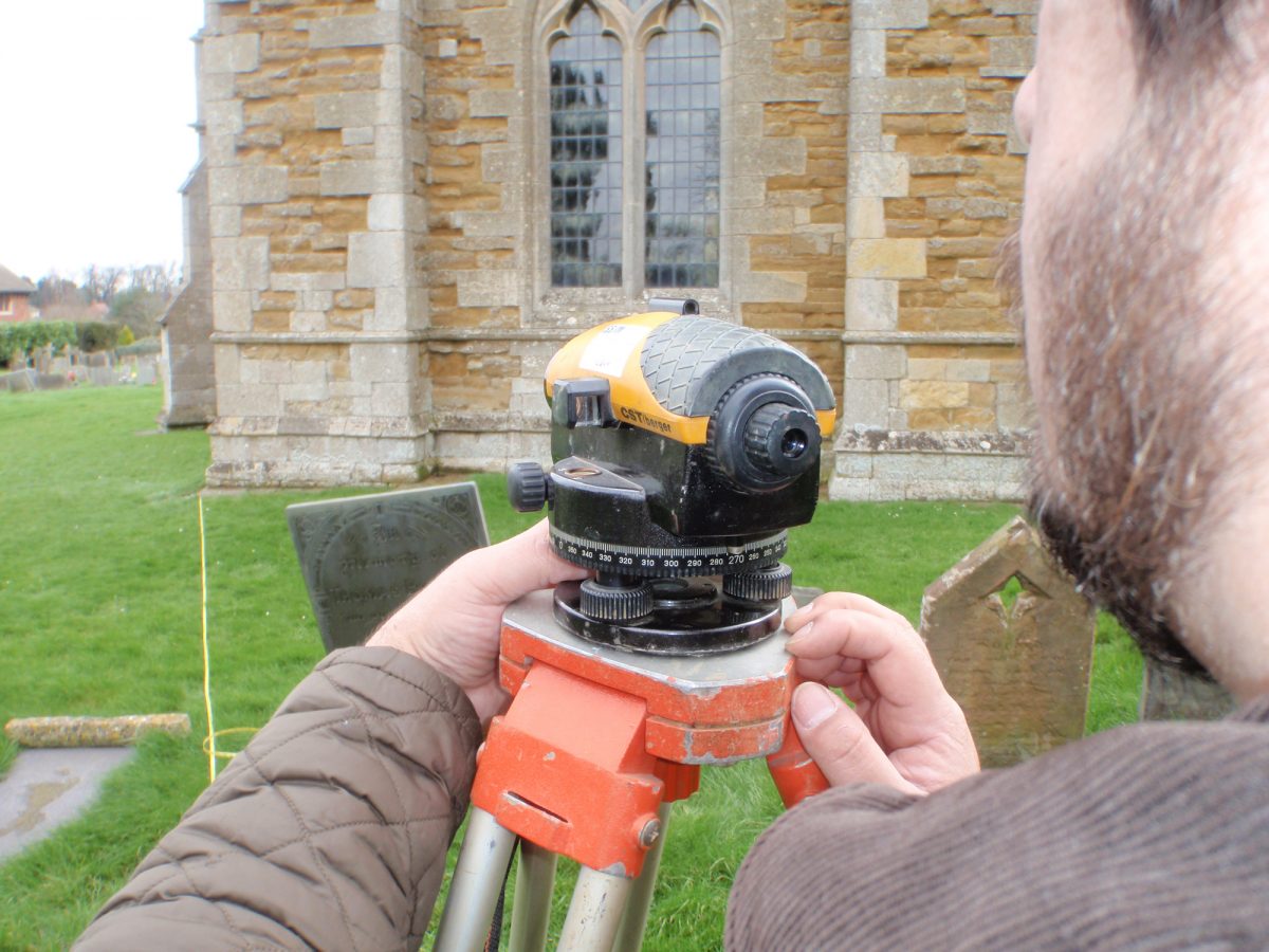
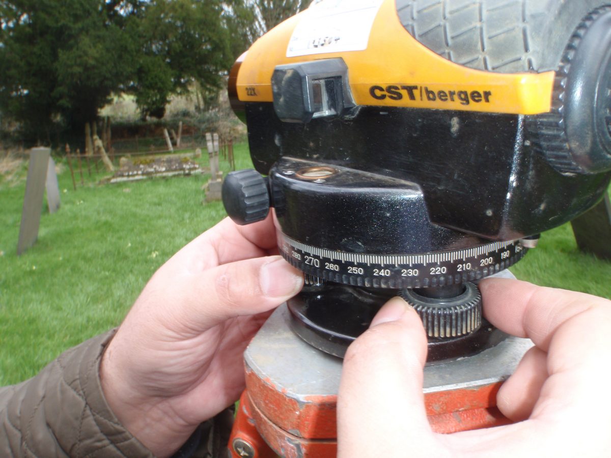
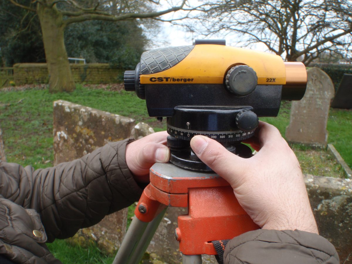
Now choose a landmark object that is approximately north of the level. Looking through the level, line the crosshairs up with that object. Without moving the level, rotate the horizontal circle so that the angle indicated is at 0.
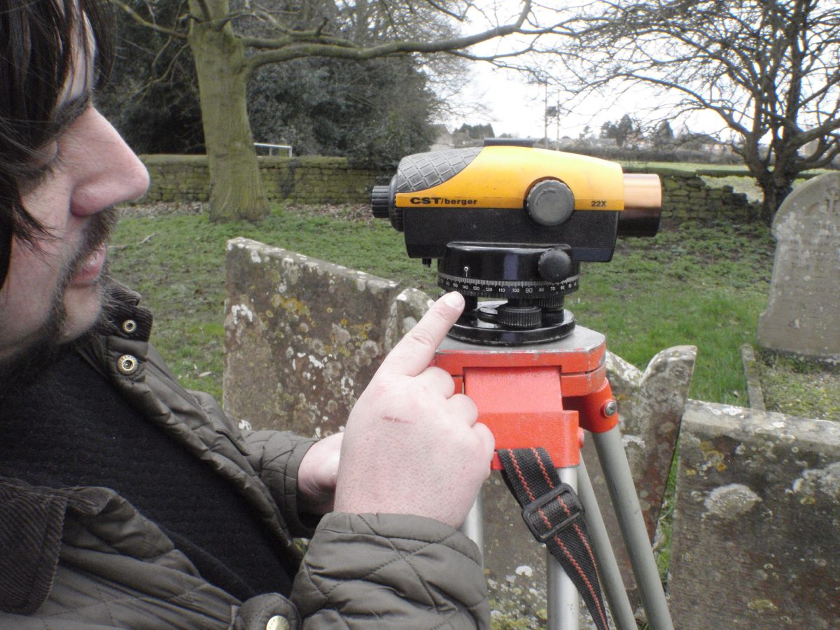
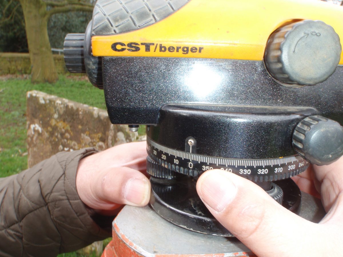
You may need to check this from time to time. The dumpy level is now ready to use.
Using a plumb line, push a nail into the ground beneath the centre of the instrument, and attach your 30m tape using a bulldog clip.
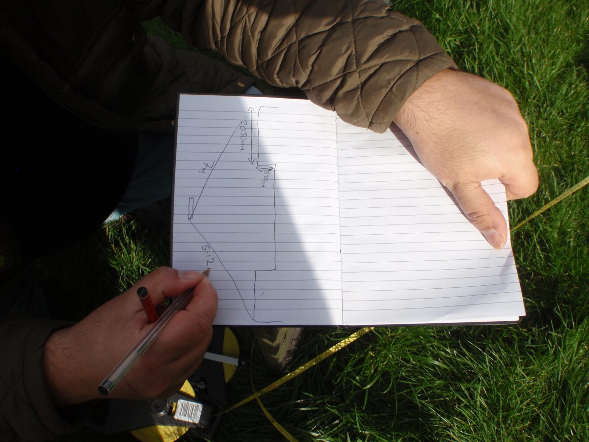
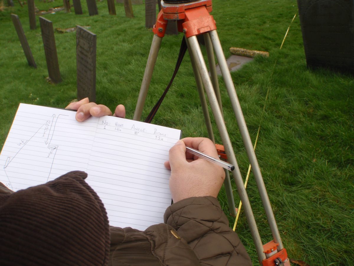
At this point it may be useful to make a quick sketch so you can keep track of what you have surveyed.
Select a point that you wish to locate on the ground and mark it with the level staff.
Now measure the distance from the centre point with the 30m tape and make a note of it. Now turn the dumpy level to see the staff. Looking through the level, adjust the focus using the knob on the side of the level.
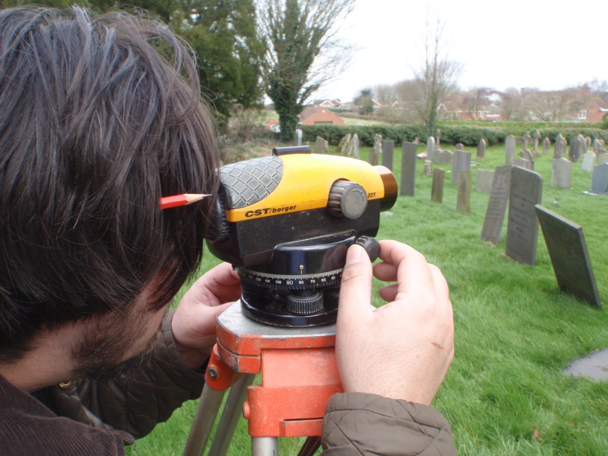
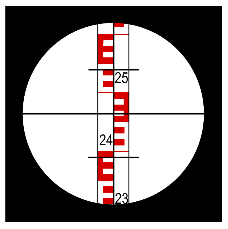
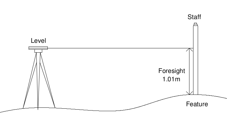
Using the crosshair line visible through the level, align the vertical crosshair with the centre of the staff. Now read the angle from the horizontal circle, and make a note next to the distance measurement. Now look through the level again and make a note of the position of the horizontal cross hair, and make a note of that. This is known as the foresight and is used to calculate height above sea level.
Repeat this process for each point.
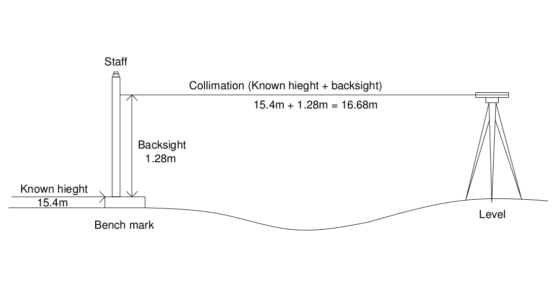
At the end of the survey (from this base point), you will need a reference height (bench mark). Find a point that you will be able to locate on an internet map site, such as the side of a road and take the height reading from the staff without measuring the distance. This is known the back sight.
After the survey is finished and you are able to access a computer with internet access, log on to the site https://www.freemaptools.com/elevation-finder.htm and use the satellite image to find where your reference height point. Put your cursor on that point and left click. At the bottom of the picture will be the height above sea level in m.
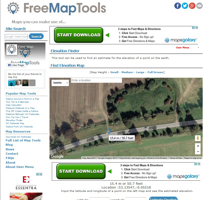
From this it is possible to calculate the height above sea level of every point of your survey. This is a fairly simple mathematical operation, once you understand the logic behind it.
First, let’s be clear about what we are working out. For each point, we want to know the height above sea level of the ground on which the staff is placed. The measurement you have recorded (fore sight), the difference between middle of the eyepiece of the dumpy level, and the ground at the point that the staff is positioned.
If you have taken a staff reading (back sight) on a point of known height above sea level (bench mark), you can work out the height above sea level of the middle of the eyepiece of the dumpy level. This is the height above sea level of that point, plus the reading on the staff, and is known as the collimation.
Now we know the different between the collimation and the height of a particular point because this is the fore sight. So, if we subtract the fore sight from the collimation, we will have the height above sea level of that point. This is known as a reduced level.
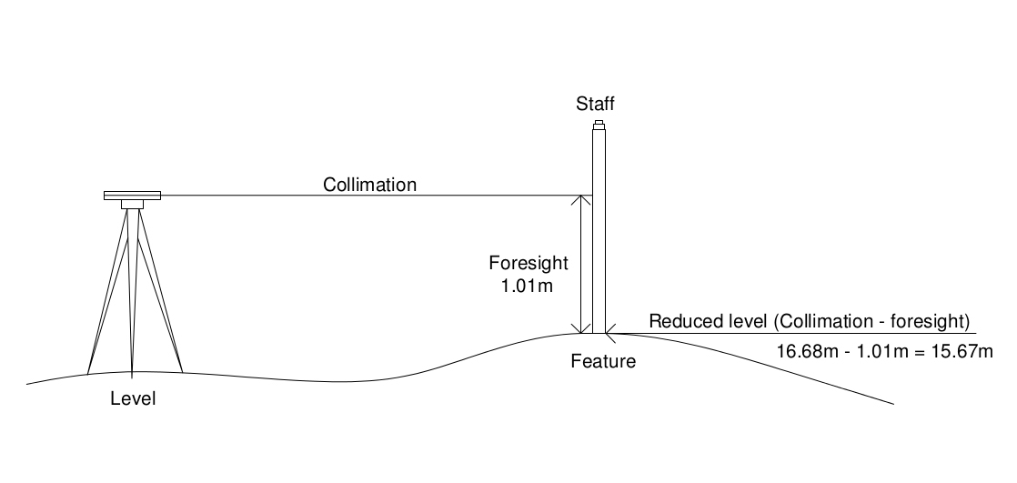
Work through the example in the drawings for yourself, you may find it easier to understand if you make your own drawings.
Other survey techniques
As well as the techniques described above, there are a number devices that allow rapid survey over large areas. The most commonly used currently, is the Global Positioning System or GPS. Survey grade GPS equipment is expensive, and although it will be demonstrated and used on some of the study sites, it will not form a technique that you can use on your own with loaned equipment.